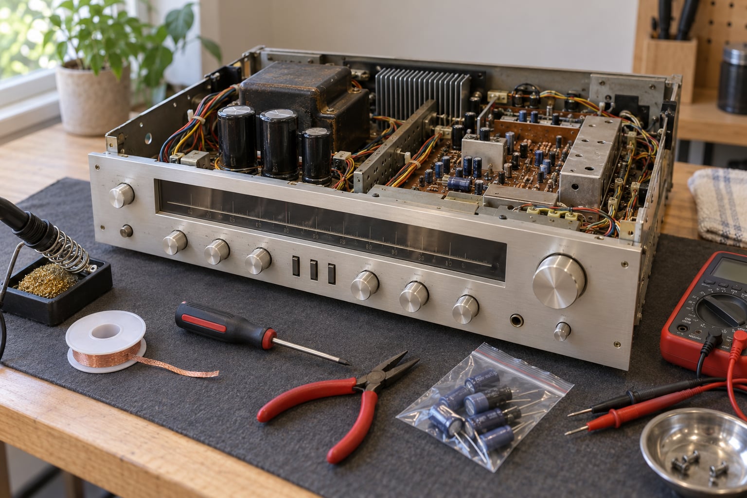
Learning how to replace capacitors in a vintage receiver is mostly mechanical: unplug it, discharge the filter capacitors, desolder the old cans one at a time, and solder modern parts in their place. The soldering is the easy half. The half that matters is deciding which capacitors to touch, matching polarity and voltage correctly, and treating the power supply as live even when the unit is switched off. A receiver built in the 1960s or 1970s can still hold several hundred volts behind the rectifier for weeks after it is unplugged, so the safety steps are not optional.
Most first-time restorers get stuck on two things rather than the solder itself. The first is part identification, because a chassis can hold forty to eighty electrolytics and nothing on the board labels which ones matter. The second is physical mounting, because modern capacitors are much smaller than the cans they replace and something has to hold them in place.
This guide works through both, in the order you should actually do them. It assumes you already own a soldering iron and are comfortable with a multimeter. If you have never soldered anything, practise on a scrap board first. If the receiver uses mains voltage directly and you have no idea what a rectifier or a filter capacitor is, that is a job for a technician, not a weekend.
Table of Contents
- What You Need
- Documentation and identification
- Tools
- Parts
- Safety gear
- How to read the old capacitor and match a replacement
- What not to replace
- Step-by-Step: How to Replace Capacitors in a Vintage Receiver
- 1. Identify the receiver and confirm the symptoms
- 2. Unplug the receiver and discharge the power supply safely
- 3. Locate and identify the capacitors
- 4. How to replace capacitors in a vintage receiver without lifting pads
- 5. Inspect and test before reassembly
- 6. Reconnect the power supply and perform an initial test
- 7. Reassemble and evaluate the restored sound
- Common Mistakes
- Frequently Asked Questions
- Can I replace capacitors in a vintage receiver without a service manual?
- Are all capacitors in a vintage receiver bad?
- What happens if I install a replacement capacitor backward?
- How do I remove a capacitor from a receiver board?
- How long does a receiver recap take?
- Conclusion: Replace One Section at a Time
What You Need
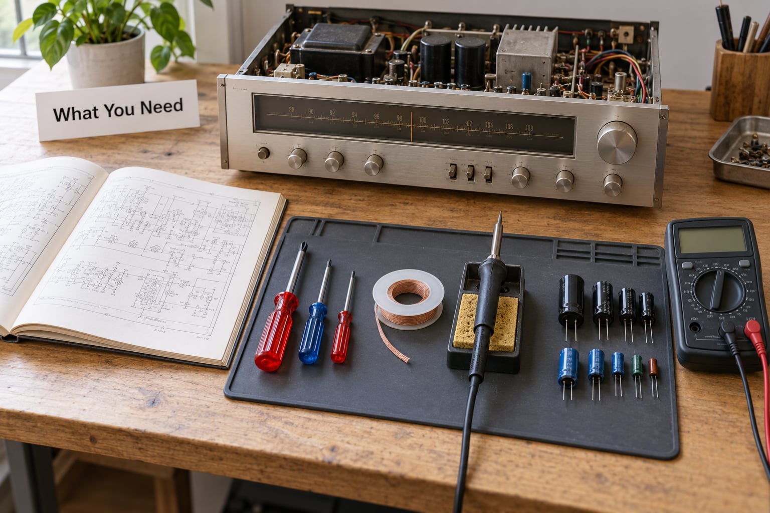
Everything below is cheap except the capacitors themselves, and none of it is optional. Gather it all before you remove the case so the receiver is not sitting open on the bench while you go looking for a tool.
Documentation and identification
The service manual for your model is the single most useful item on this list. It shows the circuit groups, marks the polarity of the power supply capacitors, and lists the original parts. If the original manual is gone, a schematic from a parts supplier or a scanned copy in a vintage audio forum is still worth having.
A phone or camera for photographs comes next. Photograph every board before you desolder anything, then photograph each capacitor position at close range so the stripe, the polarity mark, and the surrounding components are all legible later.
Tools
A temperature-controlled soldering iron in the 25 to 40 watt range, with a fine tip, does the actual work. A desoldering braid or a solder sucker removes old joints without lifting pads, which matters because many boards of this era use single-sided copper that tears easily. Add flux, a small brush, and 99 percent isopropyl alcohol for cleaning residue off the board.
A multimeter is required rather than optional. You use it to check for voltage across the filter capacitors before you touch anything, and afterwards to confirm that a discharge resistor is doing its job. Needle-nose pliers, side cutters, and a small screwdriver set round out the kit.
An ESR meter is optional but genuinely useful. It tells you whether an electrolytic still has acceptable internal resistance, which is often the reason a receiver hums even though the capacitance looks close to spec. A capacitance meter is a nice addition for checking a part before you install it. For the first power-up, a dim-bulb tester or a current clamp helps you watch inrush current without risking the rectifier.
Parts
Replacement capacitors in the values and voltages the manual calls for, ordered from a reputable distributor such as Mouser, Digi-Key, or a specialist parts supplier rather than a general marketplace where counterfeit electrolytics are common. A small terminal strip or a handful of machine screws for mounting modern parts underneath the chassis. Heat-shrink tubing or insulating sleeving to cover exposed leads, and stiff wire or small spacers to keep components clear of the chassis underside.
Safety gear
An insulated work mat, safety glasses, and gloves you can pull off in a hurry. A resistor of about 10k ohms rated for a few watts is your discharge tool, used with an insulated probe rather than a bare screwdriver. Keep one hand off the chassis whenever the set is powered. That habit, more than any particular technique, is what keeps a mistake from becoming an injury.
How to read the old capacitor and match a replacement
Old electrolytic cans print their values clearly enough once you know the layout: capacitance in microfarads, then working voltage, then temperature and brand. A can marked 4700 35V is 4700 microfarads rated at 35 volts. A mark reading 105C tells you the temperature rating, which is useful mainly as a clue about the original part quality. Look for a stripe, band, or plus sign that identifies the negative terminal, and note the lead length and spacing on the old part before you remove it.
Now pick the replacement. Match the capacitance exactly where the value is a standard modern number, or use the nearest lower value in the same series, then go one voltage rating higher than the original, never lower. A 4700 microfarad 35V can is fine as a 4700 microfarad 50V part. Specify a 105 degree low impedance electrolytic from a known maker, and treat heavily counterfeited brands as a category to avoid.
Older values are frequently unavailable. The usual substitutions run to the next value down: 5 microfarads becomes 4.7, 25 becomes 22, 100 becomes 82 or stays at 100, and 0.1 microfarad becomes 100 nanofarad. Small drops like these are electrically harmless in almost every audio position. Moving to a much higher voltage rating than the original does nothing useful, though, and can push the part out of its intended physical size class.
What not to replace
Leave paper and wax capacitors inside the RF and tuner sections alone. They are part of an aligned circuit, and substituting a modern part shifts the alignment permanently. The same goes for dogbone and tubular ceramics in the RF path, and for anything around the tuner gang. Experienced restorers consistently put the tuner last and often skip it entirely.
Film and ceramic capacitors in the audio path are usually still fine, and swapping good ones for exotic parts is a common way to waste a weekend. The parts worth replacing are the aging electrolytics and older tantalum capacitors, working from the power supply outward through the rest of the chassis.
Step-by-Step: How to Replace Capacitors in a Vintage Receiver
Work through these stages in order, and finish one section before opening the next. Rushing the order is what turns a two-hour power supply job into a weekend of chasing a second fault.
1. Identify the receiver and confirm the symptoms
Write down the make, model, and chassis number, then find the service information for that exact model. Confirm that the fault is actually capacitor related before you order parts.
Hum that follows the volume control rather than the input, a receiver that needs several minutes to warm up before it settles, loss of low-end weight, crackling in one channel, or a dead channel with no output are the classic signatures. So are weak output and a general loss of dynamics. None of these prove a capacitor is the cause, though, and it is worth ruling out tubes, a failed speaker, a dirty selector switch, or a broken dial cord before ordering anything. A dry selector switch produces channel-cracking noise that gets mistaken for a bad coupling capacitor constantly.
If the receiver works perfectly and you are recapping purely as preventive maintenance, say so honestly to yourself first. Plenty of well-made 50-year-old filter capacitors test good and are still in spec. A partial recap gives false confidence, so the sensible options are a complete electrolytic recap of the audio sections, or leaving the unit alone until a symptom shows up.
2. Unplug the receiver and discharge the power supply safely
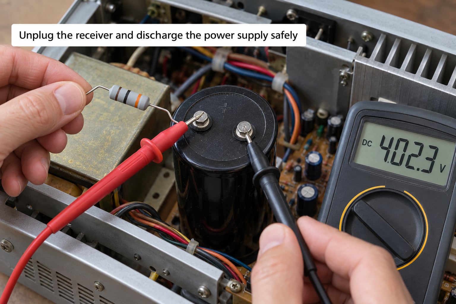
Pull the mains plug out of the wall and leave it visibly disconnected. Switch the set off as well, because some units route power through the switch rather than the plug alone. Wait several minutes before touching anything inside, then measure DC volts across the largest filter capacitor in the power supply with your meter set high, then lower, until you find the range that gives a readable number.
If it reads more than a volt or two, discharge it properly. A 10k resistor of 2 watts or more is enough for most receiver supplies, higher wattage for the big cans. Connect it across the capacitor, leave it for a minute or two, and re-measure. Repeat until the meter reads near zero, and keep the resistor connected while you work nearby so nothing can recharge it.
A receiver with a tube power amplifier runs at higher voltages than a solid state set, and the rectifier and second filter can hold that charge much longer than you expect. Shorting a charged can with a screwdriver or a pair of pliers is the classic way people get seriously hurt, and the “it went pop and the fuse blew” outcome is the lucky version. Work with one hand only when the set is live, keep the other away from the chassis, and if you are ever unsure whether something is discharged, treat it as charged.
3. Locate and identify the capacitors
Physical appearance is not a reliable guide. A large can in the corner near the transformer is almost always a main filter capacitor, but the smaller parts around it vary by circuit. Use the manual or the board layout to group the capacitors by circuit, then confirm with circuit tracing where a schematic exists: follow the trace from one terminal to see what the part connects to.
Replace in this order, which follows the priority most restorers agree on. Start with the main power supply filter capacitors and the rectifier area. Move next to the protection and relay circuits, then the power amplifier boards and their bias and DC offset supplies. After that come the preamp and phono equalising stages, then the tone control and filter boards. Leave the tuner for last, and only if the symptoms point that way.
That order matters because the power supply is the section most likely to be the actual fault, it carries the highest ripple current, and a mistake there is the one most likely to damage the rectifier. Testing the supply first also gives you a stable reference for everything downstream.
Make a list as you go: position, old value, old voltage, and the board or section it belongs to. Count the capacitors before you start so you know how many you expect to remove, and photograph each one in place before touching it.
4. How to replace capacitors in a vintage receiver without lifting pads
Desolder one capacitor at a time and only one section at a time. Photograph each part in place first, marking the negative side clearly in the image, and note whether the original was radial or axial, screw terminal, snap-in, or solder tab.
To remove a solder-tab or radial part, heat the joint on one side, add fresh solder, and wick it away with desoldering braid so the hole cools quickly, then repeat on the other lead. Do not hold the iron on a pad longer than a second or two. Old boards often use single-sided copper with weak adhesion, and pads lift when they overheat. If a pad lifts, stop, stop desoldering in that area, and repair it before going further.
For screw terminal and snap-in parts, unscrew the terminal from the old body, note which terminal went to which side, and pull it free. This is where most people damage a receiver, because the old can body is often the only thing holding those two screws into the board.
Inspect the old capacitor before discarding it. Leaked electrolyte leaves a crusty, oily film, and a bulging, cracked, or browned can tells you what the circuit was doing while the part failed. Note the polarity for the replacement: the stripe, band, or notched side on an electrolytic marks the negative terminal, and on an axial part the stripe runs down the side nearest that lead.
Solder the new capacitor in with the correct polarity, matching the original orientation. If you can only find a part with the opposite lead spacing or a physically smaller body, mount a small terminal strip near the old location and run extended leads to the new capacitor, which can then hang underneath the chassis. Standoffs, a small perfboard offcut, or re-using the old can body as a shell are the other usual approaches. Whatever you use, keep the part clear of sharp chassis edges and other components so nothing works loose over a decade of vibration.
Do not push the new electrolytic hard against the board or twist its leads to reach a pad. Mechanical stress on the seal is a slow leak, and a leaked capacitor in a warm spot can fail the whole rebuild quietly.
5. Inspect and test before reassembly
Leave the chassis open and look at every joint you made. Check polarity against your photographs, confirm no leads are pinched or touching, look for solder bridges between adjacent pads, and make sure nothing is bent back where it can chafe against the chassis underside. Give the board a clean with isopropyl alcohol and a brush so any flux residue or leaked electrolyte comes away.
Then measure. With the set still unplugged, a resistance check between the capacitor leads and from each lead to chassis can catch a reversed part or a short before you apply power. Where the design allows a resistance or leakage test in circuit, that is usually enough for a first pass; ESR in circuit gives less reliable readings because parallel paths interfere, so lift one lead when you want a number you trust. Discharging a test part before measuring it matters as much here as it did on the bench.
6. Reconnect the power supply and perform an initial test
This is the moment where care pays off. If you have a variac or a dim-bulb tester, bring the receiver up slowly through it and watch what happens. Otherwise plug it in with your hand near the switch and the meter ready, and be ready to pull power immediately.
Watch for a heavy inrush on first power-up, which is normal while the filter capacitors charge. What is not normal is a rapidly cycling or blown fuse, a burning smell, smoke, a rectifier or power transistor that gets hot to the touch within seconds, or a hum that gets worse instead of fading as the set warms. Any of those, switch it off at the wall rather than at the panel.
After it has warmed up, measure the DC across the main filter capacitor and compare it with the voltage noted in the service manual. A reading far above the rail suggests a shorted or leaky part is still in the circuit. Check the DC offset at the speaker terminals if the manual gives a figure, and check idle current or bias on a tube amplifier. A recap changes the DC operating conditions, so bias and offset that were correct before may need resetting afterwards.
Listen for hum before you judge anything else. Strong mains hum that scales with the volume control points straight back at the power supply section, usually a filter capacitor or a ground connection you disturbed.
7. Reassemble and evaluate the restored sound
Refit the boards, the dial glass, the knobs, and the tubes, and reconnect any wiring loom you unplugged. Restore the fuse to its correct rating if you changed it during testing. Check the controls, the selector switch, and both speakers while you have the room open, since a scratchy control or a loose speaker terminal can masquerade as a recap problem.
Give the receiver a proper evaluation rather than deciding in the first ten minutes. Volume and tone controls may need cleaning, the phono stage may need recalibration if its capacitors changed, and the tuner may want a moment to warm up before it holds stations. Listen across several sessions on familiar material and with the system in a known-good state, so you are judging the receiver rather than the recording or the speakers.
If a channel now sounds noticeably different from the other, that is a common and usually solvable symptom of the work. Recheck polarity on the parts in that channel, then look at the bias or offset setting for that amplifier board.
Common Mistakes
Reading polarity from memory instead of a photograph. This is the single most damaging error, because a reversed electrolytic heats up fast and can take the rectifier or a transistor with it. Photograph before removal, mark the negative side in the image, and match it rather than trusting memory or a same-looking stripe on the new part.
Guessing values that were never confirmed. Value substitution works downward within a series, not upward and not by feel. Confirm the original capacitance from the can sleeve or the manual, keep the voltage rating at or above the original, and resist the urge to fit a much larger part that will not physically fit where the old one sat.
Skipping the discharge step because the unit has been unplugged for a while. Residual charge can persist for weeks, and shorting a charged can is how people are seriously hurt. Measure before you touch, discharge with a resistor rather than a metal tool, and re-measure with the resistor left in place.
Holding the soldering iron on a pad too long. Single-sided boards of this era lift pads and tracks quickly. Use a hot, light touch, add fresh solder to speed the heat transfer, and wick it away with braid rather than pulling on the lead.
Forcing modern parts where the old ones were solder tabs. A smaller modern capacitor has nothing holding it, so the leads carry all the mechanical load and eventually crack the joint. Use a terminal strip, a standoff, or a restuffed can so the solder joints see no stress.
Replacing good parts in the tuner or RF section. Paper, wax, and dogbone ceramics inside an aligned circuit are part of the tuning behaviour. Changing them without re-alignment can leave the receiver worse than when you started.
Testing before inspecting the work. A reversed or shorted capacitor will not announce itself politely at the fuse. Walk back through every joint you made, then power up slowly and watch current draw before listening to anything.
Recapping the whole chassis in one afternoon. Working section by section, with the receiver tested between stages, tells you what fixed what. Replacing everything at once gives you a receiver that either works or does not, with no information in between.
Frequently Asked Questions
Can I replace capacitors in a vintage receiver without a service manual?
It is possible, but a manual makes the job far easier and safer. Without one you are inferring capacitance, voltage, polarity, and circuit location from the board itself, which is slow and easy to get wrong. A schematic from a parts supplier or a scanned copy online is enough for most receivers, and it turns a guessing exercise into a checklist.
Are all capacitors in a vintage receiver bad?
No. Electrolytics fail at different rates depending on type, voltage, temperature, age, build quality, and position in the circuit. A large, well-made filter capacitor that tests good may still be in spec after fifty years. Replace the ones that are leaking, bulging, cracked, or out of specification, and treat the rest of the electrolytics as aging rather than failed.
What happens if I install a replacement capacitor backward?
A polarized electrolytic installed backwards will overheat quickly, may leak, and can destroy the rectifier, a transistor, or the board trace around it. Some units simply fail to start; others fail dramatically. Photograph the original orientation, match the negative stripe to the schematic or board marking, and check every part again with the power off before you power up.
How do I remove a capacitor from a receiver board?
Heat one joint, add fresh solder, then wick the molten solder away with desoldering braid so the pad cools fast, and repeat on the other lead. Avoid pulling hard on the component, and never hold the iron on one pad for more than a second or two. Screwed terminal and snap-in parts unscrew instead of desolder, so note which side each terminal went to first.
How long does a receiver recap take?
A power supply rebuild on a typical receiver takes an experienced hobbyist two to four hours including testing, and a full electrolytic recap of a larger chassis takes a full weekend. First-time restorers spend much of that extra time on identification, mounting smaller modern parts, and cleaning residue, so allow a full day and work in sections rather than all at once.
Conclusion: Replace One Section at a Time
The safe order never changes: document the receiver, confirm the symptoms really point to capacitors, unplug and discharge, photograph every position, then work outward from the power supply one circuit group at a time, testing between stages. Start with identification rather than ordering parts, because the manual tells you which capacitors are worth replacing and which are better left alone.
Two things earn a technician instead. The first is a receiver with a high-voltage tube power amplifier if you have never discharged a filter capacitor safely. The second is any unit whose value or condition makes a mistake expensive. A part you can replace is a mistake you learn from; a rare chassis is not.